Introduction background
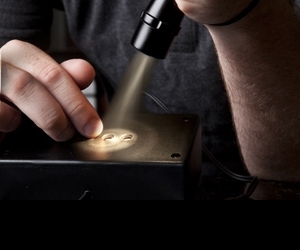
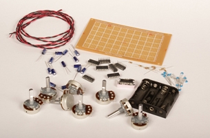
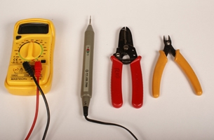
Set Up materials and tools

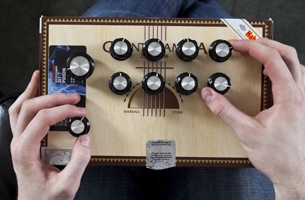
Make It project specs
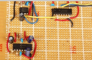
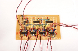
1 prep the circuit
-
a.
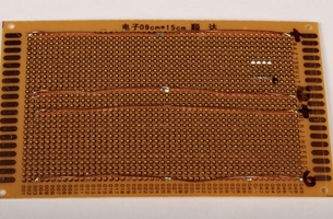
Fit the circuit board into the case you’ve chosen. If it does not fit, cut the board to size, leaving room for battery the holder to be placed into the box beside the circuit. Make sure there is clearance for the wiring and the potentiometers.

-
b.
Dry fit the circuit. Place all the ICs onto the circuit board making sure there is room for the wiring.
-
c.
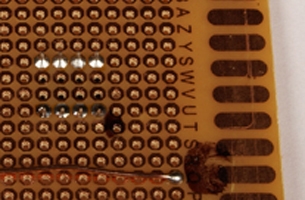
Establish power buses on the circuit board. Use solid, uninsulated hookup wire or bus wire to make positive and negative connections on the underside of the board.
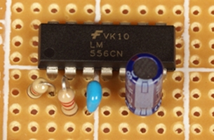
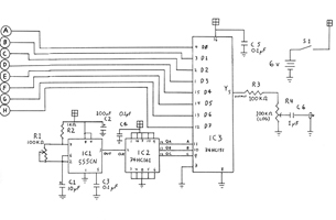
2 build the clock
![]()
-
a.
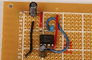
Mount the 555CN chip (IC1) on the circuit board. Make sure that pin 1 is at the lower left when looking at the board right-side up.
-
b.
Mount R2 and C1, C2, and C3 nearby.
-
c.
Make all connections to IC1 as shown in the schematic. Don’t forget the connections to the power and ground buses.
-
d.
Connect to pins 6 and 7 of 555CN chip (IC1) two pieces of stranded wire long enough to reach the potentiometer R1 when the board is installed in the case. It’s better to make these slightly long, then trim them in final assembly rather than have them too short.
-
e.
Twist these wires together and label the wires with masking tape marked tempo.
3 build the counter
-
a.
Mount the 74HC161 counter chip (IC2) near IC1. Make sure that pin 1 is at the lower left when looking at the board right-side up.
-
b.
Mount C4 as near to IC2 as possible.
-
c.
Connect one lead of C4 to pin 14 of IC2 and the other to pin 7 of IC2.
-
d.
Connect pin 14 of IC2 to the positive supply, and pin 7 of IC2 to ground.
-
e.
Make all connections to IC2 as shown in the schematic, taking careful note of which pins are tied high (connected to the positive supply), and which are tied low (connected to ground).
-
f.
Connect pin 3 of IC1 (clock output) to the pin 2 of IC2 (clock input).
4 build the data selector
-
a.
Mount 74HC151 data selector chip (IC3), beside IC2. Make sure that pin 1 is at the lower left when looking at the board right-side up.
-
b.
Mount C5 as near to IC3 as possible.
-
c.
Connect one lead of C5 to pin 14 of IC3 and the other to pin 7 of IC3.
-
d.
Connect pin 14 of IC3 to the positive supply, and pin 7 of IC3 to ground.
-
e.
Connect pin 6 of IC3 to pin 7 of IC3.
-
f.
Connect the outputs QA, QB, and QC of IC2, to the inputs A, B, and C of IC3 as shown on the schematic.
-
g.
Mount R3 and C6 near IC3, and wire them as shown on the schematic:
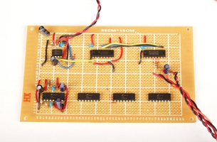
6 build the oscillator
-
a.
Mount the 556C dual-timer chip (IC4) on the circuit board. Make sure that pin 1 is at the lower left when looking at the board right-side up.
-
b.
Mount R5, R6, C8, and C9 near the pins 1 through 7 on the one side of IC4.
-
c.
Mount R8, R9, C10, and C11 near pins 8 though 14 on the other side of IC4.
-
d.
Install C7 near pin 14 of IC4.
-
e.
Make the pin-to-pin connections on IC4.
-
f.
Connect the various resistors and capacitors to their associated pins, and also to + or ground, as applicable.
-
g.
Connect pin 5 of IC4 to pin 4 of IC3 (the first data input: D0).
-
h.
Connect pin 9 of IC4 to pin 3 of IC3 (the second data input: D1).
-
i.
Connect a long pair of leads from one side of R6 and pin 2 of IC4 as was done for the clock circuit.
-
j.
Twist these two wires together and label with masking tape marked R7.
-
k.
Connect a long pair of leads from one side of R9 and pin 12 of IC4.
-
l.
Twist these two wires together and label with masking tape marked R10.
-
m.
Repeat steps 5a to 5l to connect ICs 5, 6, and 7.

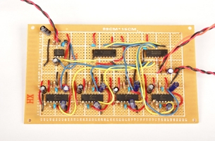
6 final assembly
-
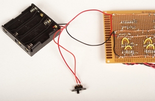
a.
Connect the black negative wire of the battery pack to the ground rail(s) of your circuit.
-
b.
Connect the red positive wire to one side of switch S1, and the other side of S1 to the positive supply rail(s) of your circuit. If you have used multiple supply rails, make sure they are all properly connected.
-
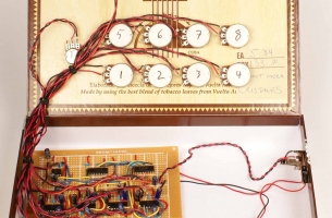
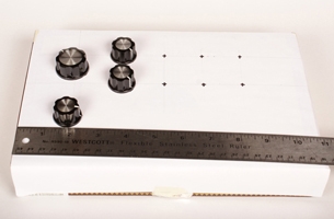
c.
Mount the potentiometers in the case. You will need room for the eight frequency pots, plus the tempo pot and volume pot.
-
d.
Mount S1 and the output jack.
-
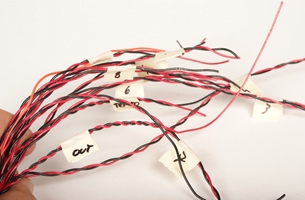
e.
Mount the circuit board in the case. You can simply use machine screws from the hardware store or special standoffs from an electronics shop.
-
f.
Connect the pair of wires from IC1 to lugs 1 and 2 of the tempo potentiometer (R1).
-
g.
Connect a short piece of wire between lugs 2 and 3 of the tempo potentiometer.
-
h.
Connect the eight pairs of wires from the oscillator section to the frequency potentiometers: R7, R10, R13, R16, R19, R22, R25, and R28, ensuring that the wires from the oscillators connect to the correct lugs on the potentiometers, 1 and 2 as in the oscillator schematic.
-
i.
Connect a short piece of wire between lugs 2 and 3 on each potentiometer.
-
j.
Connect the volume potentiometer leads from 4g–v to the volume pot, ensuring the wire from R3 goes to lug 1, the wire from the – side of C6 goes to lug 2, and the wire from ground to lug 3.
-
k.
Connect the pair of wires from step 4g–viii to the output jack, ensuring that the ground wire is on the ground lead, and the wire from the – side of C6 goes to the tip, or hot lead.
7 test your circuit
-
a.
Connect the unit to an amplifier, and turn it on. Turn up the volume potentiometer, until you hear sound. If you hear nothing, immediately turn the circuit off, and proceed to the troubleshooting section.
-
b.
Adjust R1 to near the lowest level, you should be able to hear the sequencer stepping through tones. Make sure there are no gaps you should be able to hear each oscillator in turn. Check that the tempo potentiometer controls the rate, and that each frequency potentiometer increases the frequency when turned clockwise.
-
c.
If anything seems amiss, turn the circuit off, and proceed to the troubleshooting section.
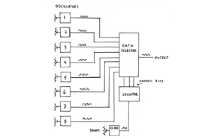
How It Works three basic building blocks of digital circuits
and so on.
Help! troubleshooting
-
a.
Touch each chip as if you were touching a hot iron.
-
b.
If you find a hot chip, turn the power off and solve the problem before turning it back on.
-
c.
A hot chip is usually caused by a backward connection or an output shorted to one of the power rails.
-
d.
Check the power and ground connections to each chip with a voltmeter. Or, using a logic probe, verify that the power pins are at a “high” level (usually indicated by a red light) and ground is at a “low” level (green). An indication of neither high nor low indicated by a “floating” pin, which could be a problem.
-
e.
Check that the audio output is connected properly and is not shorted out. A logic probe on pin 5 of IC4 should show both high and low lights on.
-
f.
Check pin 3 of IC1 with a logic probe to verify that it the signal is changing from high to low at a rate that you can easily see with the logic probe. Verify that this same signal appears at pin 2 of IC2 and on pin 14 of IC2. A signal with half the rate should appear on pin 13 of IC2. And a signal with half that rate (one-quarter of the rate at pin 2) should appear on pin 12.
-
g.
If these signals are not present, check that all the pins of the IC2 that should be tied high or low are at the correct levels. If these signals are correct, verify that they are reaching pins 11, 10 and 9 of IC3, and that all of IC3s pins are at the correct levels.
If one or more tones missing:
-
h.
Check the outputs (pins 5 and 9) of the 556 chips in the oscillator section of the circuit with the logic probe. You should see both the “high” and “low” lights on simultaneously. This shows you that the circuit is oscillating (at a rate too fast for your eyes to see). If you are checking the outputs with an oscilloscope, you should see a square wave. If either the “high” light or “low” light is on, or if neither light is lit, then there is a problem.
-
i.
Check that the output signals above show up on the appropriate input pins of the IC3. If an oscillator is lacking an output, or the output is there but not showing up on the input of IC3, check the connections and the part values associated with that oscillator and the connections to IC3
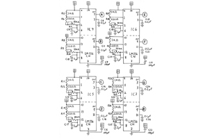
Reference oscillator schematic

Reference clock, counter, and data selector schematic
Reference glossary