Introduction background
Get out your sewing basket and your electronics toolkit, and get ready to make a soft-circuit sound sculpture. For a lot of people these days, the sewing kit is the electronics kit! Our Octopurse project will introduce you to the world of electronic textiles. Electronic textiles, also called e-textiles, are part of a broader category of wearable electronics, or wearables. Many wearables projects embrace the idea of ubiquitous computing, the idea that everyday objects will be embedded with intelligence, and our interactions with them will be seamless. The smart phone that you carry in your pocket is a step in this direction, but imagine if you didn’t have to remember to put it in your pocket in the first place, or to remember to take it out when you washed your jeans?

Other projects (as is ours) are about augmenting traditional craft techniques with modern electronics. Motivations for this sort of work can range from critical thinking about gender roles in craft and engineering to simple delight in an object that lights up or makes a sound. Of course, there’s no hard line dividing these two approaches, and a lot of the best work in the field combines sophisticated engineering with high-level fashion design and fabrication. In recent years, microcontroller platforms specifically designed for wearables—such as Leigh Buechley’s LilyPad Arduino—have appeared on the market, making it easy to sew some intelligence into a project.
Our project doesn’t have any intelligence. It’s just a pair of oscillators controlled by touch contacts, but it will serve as a good introduction to working with conductive thread. Like most wearables projects, ours is going to need both textile and electronic fabrication techniques. Whether you’re new to sewing or to soldering or to both, you’ll no doubt pick up some new skills. We made a purse with an octopus design, but of course you can adapt this to all kinds of textile art, such as cushions or jackets.
Set Up materials and tools
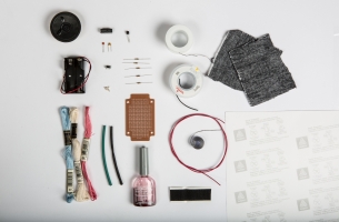
[A] 1 8Ω (8-ohm) speaker, small enough to be sewn into your project.
[B] 1 battery holder for 2 AA batteries. AAA with appropriate holder will work, too—and will be smaller and lighter!
[C] Embroidery thread to embellish your design. We used 1 skein each of DMC 6-strand floss in hot pink, baby blue, and white.
[D] 2 3-inch lengths of 1/8-inch heat-shrink tubing.
[E] 8 crimp beads.
[F] 1 small switch.
[G] 1 0.001µF (0.001 microfarad) capacitor, designated C1.
[H] 1 0.047µF (0.047 microfarad) capacitor, designated C2.
[I] 1 74HC132 quad 2-input Schmitt trigger NAND gate. It’s important to use the Schmitt trigger version, rather than a regular NAND gate.
[J] 1 2N3904 transistor.
[K] 5 resistors: 2 1MΩ, designated R1 and R3; 2 1KΩ, designated R2 and R4; and 1 220Ω, designated R5.

[L] 1 small piece of circuit board.
[M] 1 bottle of clear nail polish.
[N] 1 12-inch length of adhesive-backed Velcro.
[O] 6 feet of 24-gauge stranded hookup wire.
[P] Conductive thread. We used catalogue number DEV-10867 from SparkFun Electronics. Catalogue number 603 from Adafruit would also be suitable.
[Q] 6 feet of 22- or 24-gauge solid hookup wire.
[R] 1 rosin-core electronics solder (consider using the lead-free variety).
[S] 2 3-inch squares of your choice of fabric.
[T] 1 8-1/2-x-11-inch sheet of iron-on transfer paper. We used Avery Inkjet Dark T-shirt Transfers.
[U] 1 small, black, messenger-style purse.
[V] Batteries to fit holder for either AAs or AAAs (not pictured).
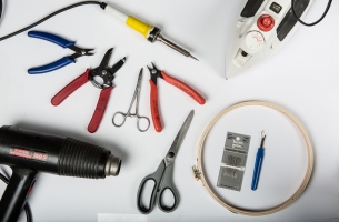
[W] Soldering iron, 35 watts or less, or a temperature-controlled soldering station.
[X] Clothes iron.
[Y] Embroidery hoop (optional).
[Z] Seam ripper.
[AA] Medium-gauge embroidery needles.
[BB] Scissors.
[CC] Heat gun.
[DD] Crimping pliers.
[EE] Wire strippers suitable for small-gauge wire.
[FF] Locking forceps or needle-nose pliers.
[GG] Wire cutters suitable for small-gauge wire.
Make It project specifications

Time Required: a weekend (12 hours).
Complexity: medium.
Cost: 20 dollars or less.
What you need to know: how to solder, electronic construction techniques, the basics of integrated circuits, and basic sewing and embroidery.
Note: Due to the complexity of the circuit, wire-by-wire instructions are not detailed. Ensure that you have read and understood all the instructions before you begin. A good way to proceed is to make a copy of the schematic, and as you install each part and make each connection, mark it with a highlighter on the schematic. That way you can see at a glance if you’ve forgotten something, and it makes it easy to keep track of where you are, which is especially helpful if you are building the project over several days. Make sure to read the linked tutorial “How to Work with a Circuit Board,” if you are unfamiliar with the techniques required.
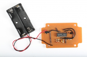
1 install the chip
Note: We’ll build the circuit as a module that will then be attached to the textile piece. You can, of course, do the textile part first, and the electronics second, if you prefer.
![]()
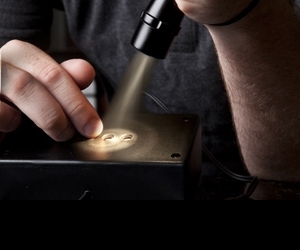
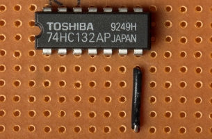
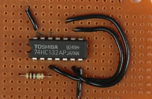
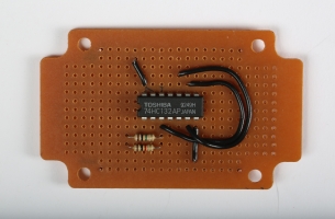
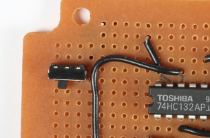
a. Identify pin 1 of the 74HC132 chip. The key to identifying the pins is finding pin 1, which is to the left of the semicircular notch at the end of the chip. The remaining pins are numbered 2 through 14 in a counterclockwise direction around the chip, viewed from above.
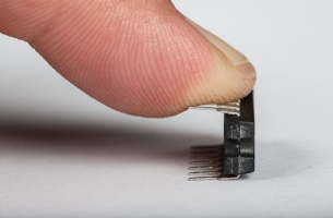
b. Straighten the pins of the chip, ensuring that they’re at right angles by slightly bending them on a flat surface, as shown.
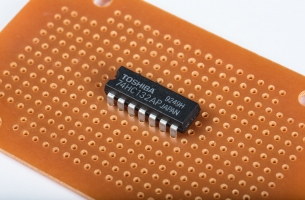
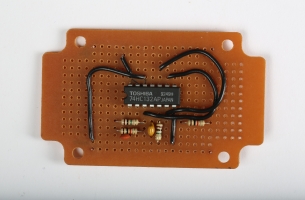
c. Solder the 74HC132 chip into the centre of the circuit board.
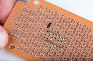
Use an indelible marker to identify pin 1 on the underside of the board. This will facilitate orientation when working on the underside of the circuit board.
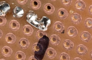
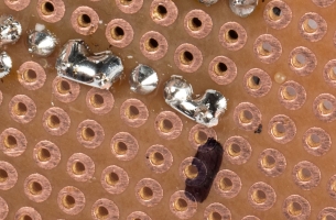
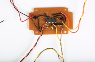
d. Use two pieces of bare wire to establish two power supply rails on the board, one for the ground supply, and one for the positive supply. Some circuit boards come with these premade in the copper pattern. The image (left) shows the positive rail soldered, and the negative one in process. Note: The ground will connect to the negative (-) side of the battery, and the positive will connect to the positive (+) side of the battery, via a switch. This will be done later, in steps 1e and 1f.
e. Use a length of insulated 22- or 24-gauge solid-core hookup wire, to solder a connection between pin 14 of the chip and the positive supply rail.
f. As in 1e, solder a connection between pin 7 of the chip and the ground supply rail.
g. Use a short piece of stripped, solid-core hookup wire on the underside of the board to solder a connection between pins 1 and 2 of the chip.
h. As in 1g, solder a connection between pins 4 and 5 of the chip.
i. As in 1g, solder a connection between pins 12 and 13 of the chip.
j. As in 1e, solder a connection between pins 3 and 9 of the chip.

k. As in 1e, solder a connection between pins 6 and 10 of the chip.
2 install the resistors and capacitors
Note: For all of steps 2 through 4, refer to the circuit schematic for clarification.
a. Solder resistor R1 (1MΩ) in place near pin 1, and then, on the underside of the board, connect one lead to the junction of pins 1 and 2, and the other lead to pin 3.
b. Solder resistor R2 (1KΩ) in place and, on the underside, connect one lead to pin 3. Leave the other lead disconnected for now.
c. Solder resistor R3 (1MΩ) in place and connect one lead to pins 4 and 5, and the other lead to pin 6.
d. Solder resistor R4 (1KΩ) in place and connect one lead to pin 6. Leave the other lead disconnected for now.
e. Solder capacitor C1 (0.001µF) onto the circuit board. On the underside of the board, connect one lead to the ground rail and the other lead to the junction of pins 1 and 2. Leave a bit of room, because we will be connecting one more wire to this point, and things can get a bit tight. Note: C1 has no polarity, so can be wired either way.
f. Solder capacitor C2 (0.047µF) onto the circuit board. On the underside of the board, connect one lead to the ground rail, and the other lead to the junction of pins 4 and 5. Again, leave a bit of room to connect one more wire here. Note: C2 has no polarity, so can be wired either way.
g. Connect the junction of pins 12 and 13 to the negative supply rail. Note that pin 11 does not get connected. Because we’re not using the whole chip in this project, we will disable pins 12 and 13 by grounding them.
h. Solder resistor R5 (220Ω) in place and connect one lead to pin 8 of the chip.
3 install the transistor
![]()
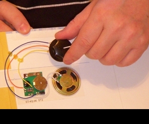
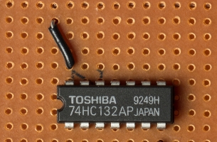
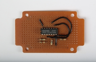
a. Examine the transistor and identify the 3 leads, which are called emitter, base, and collector, labelled E, B, and C respectively in the image (left).
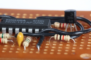
b. Solder the transistor in place, keeping it as close to the board as possible, and on the underside of the board, solder the base lead (B) to the free end of R5. Solder the emitter lead (E) to the ground rail with a short piece of insulated hookup wire.
c. Solder the switch (SW1 on the circuit schematic) in place, with one terminal soldered to the (+) supply rail.
d. If your switch has three terminals (as has the one shown), solder the red lead of the battery holder to the middle terminal of the switch. If the switch has only two terminals, solder the red lead to the free terminal. Note: Do not install the batteries in the holder at this time.
4 connect the speaker, switch, and battery holder
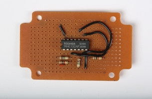
a. Solder the black lead of the battery holder to the ground rail.
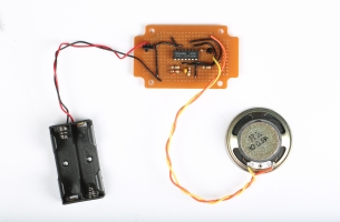
b. Solder a 6-inch length of 24-gauge stranded wire to one of the speaker terminals. Note: Some speakers come with short wires attached—they will probably be too short, so remove them and replace them with your own wire. Solder a similar piece to the other terminal. Twist the wires together, to keep them neat, and solder one wire to the (+) supply rail, and the other to the collector lead (C) of the transistor.
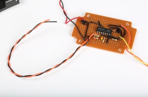
c. Solder a length of 6-inch 24-gauge stranded wire to the junction of pins 1 and 2 of the chip and R1 and C1 (point A on the schematic). Solder another length to the free end of R2 (point B on the schematic), and twist these two wires together.
d. Similarly, connect a length of stranded wire to the junction of pins 4 and 5, and R3 and C2 (point C on the schematic). Connect another length of stranded wire to the free end of R4 (point D on the schematic) and twist these two wires together.
5 test the circuit before attaching it to the messenger bag
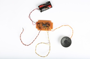
a. Place the batteries in the holder and turn on the switch. You should hear a tone from the speakers.
b. Check that the chip is not getting hot (even if you don’t hear sound from the speaker!) by touching it carefully, as you would test a hot iron. If the chip is getting hot, immediately turn the circuit off with the switch, remove the batteries, and go to the troubleshooting section of this article.
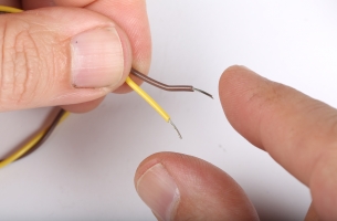
c. Squeeze between your fingers the stripped end of the first pair of wires, connected in step 4c, and you should hear the tone change. If you don’t hear a change in the sound, proceed to the troubleshooting section.
d. Squeeze the stripped end of the second pair of wires, connected in step 4d, and you should hear the tone change. If you don’t hear a sound, proceed to the troubleshooting section.
6 prep the messenger bag
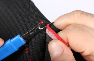
a. Use the seam ripper to remove any logos or decals sewn onto the bag.
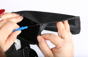
b. If the flap of the messenger bag has two layers, use the seam ripper to remove the seam that joins the two layers.
7 create and transfer the design

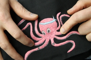
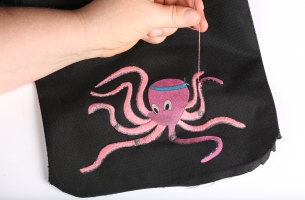
a. Create the design that you want to appear on the bag, making sure that it incorporates four points on which to place the touchpads for your instrument. We chose to hand draw an octopus, and the touchpads will be placed on four of the octopus’ legs.
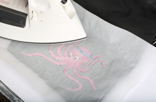
b. Transfer the design to the top flap of the bag by
i. drawing the design directly onto the top flap, using indelible ink.
ii. transfering the design to the top flap, using an iron-on transfer. We scanned our hand-drawn design and printed it onto iron-on transfer paper.
8 position and sew the touchpads
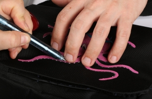
a. Use the indelible marker to set the four locations of your touchpads on the design by positioning your fingers over it. We positioned our touchpads where our fingers naturally fell on the design.
b. Cut a 12-inch piece of conductive thread, thread it through the embroidery needle, and knot one end.
c. Draw the needle and conductive thread up through the underside of the bag’s top flap, at the edge of the first touchpad, until the knotted end is taut to the flap.
d. Use a daub of clear nail polish on the knot to further secure the conductive thread to the underside of the flap.
e. Use satin stitch to embroider the first touchpad.
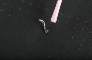
f. Do not trim the conductive thread. Leave a 4-inch length of conductive thread hanging from the underside of the embroidered touchpad.
g. Repeating steps 8b through 8f, embroider the three remaining touchpads on the top flap, where marked.
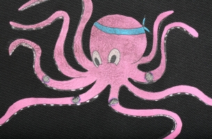
h. Embroider your design (or just leave the iron-on transfer design plain), making sure to leave space around the touchpads.
9 attach the circuit to the touchpads

a. Position your completed circuit on the underside of the bag’s top flap and match each of the four circuit leads to each of the four embroidered touchpads.
b. Strip a 1-inch length of shielding from one of the circuit leads.
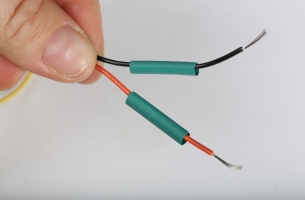
c. Slip a 1-1/4-inch length of heat-shrink tubing over the wire.
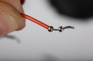
d. Thread two crimping beads onto the wire.
e. Thread an embroidery needle with the 4-inch length of conductive thread from the circuit lead’s matching touchpad.
f. Thread the needle through the crimping beads on the exposed circuit wire, drawing the needle and thread all the way though the beads and removing the needle from the thread.
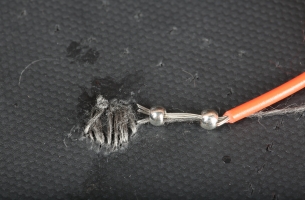
g. Pull the conductive thread so that the circuit wire is taut to the touchpad.
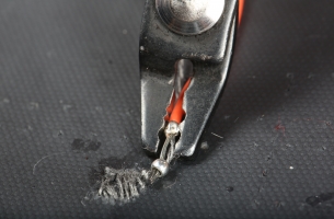
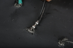
h. Using the crimping pliers, crimp the conductive thread to the circuit wire.
i. Trim the excess conductive thread.
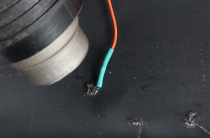
j. Lower the heat shrink over the crimped beads, thread, and wire, and shrink it in place.
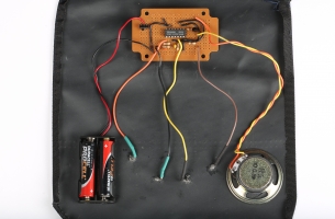
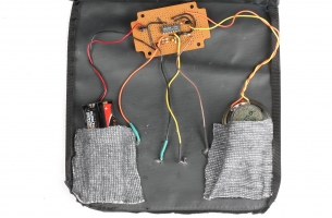
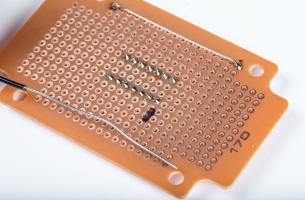
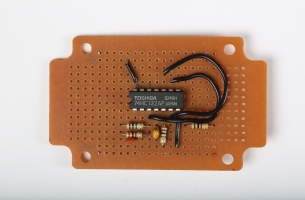
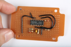
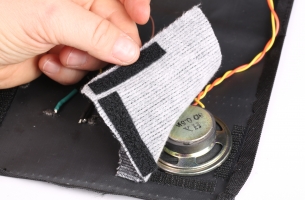
k. Repeating steps 9b through 9j, attach the remaining three circuit leads to the remaining touchpads. When your finished circuit is attached to the bag, it should look like this (left)!
10 finishing the bag
a. Affix three 2-3/4-inch hook-side strips of Velcro to three sides of a 3-inch square of fabric.
b. On the underside of lower right corner of the bag’s top flap affix the matching loop-side strips of Velcro.
c. Affix the fabric square to the underside of the flap matching the strips of Velcro. This will be a pocket for the circuit’s speaker.
d. Repeat steps 10a through 10c on the underside of the lower left corner of the bag’s top flap. This will be a pocket for the circuit’s battery holder.

e. Place the battery holder and speaker in their respective pockets.
f. Affix three 4-inch hook-side strips of Velcro to three outer edges of the bag’s top flap.
g. Using the matching loop-side strips of Velcro, affix three 4-inch hook-side strips of Velcro to three outer edges of the bag’s bottom flap.
h. Matching the strips of Velcro, press the bag’s top flap to the bottom flap. This will seal the flap of the bag, hiding the inner workings, but will also allow you to access the on–off switch by simply pulling apart the Velcro-closed flaps.
How It Works pair of square-wave oscillators
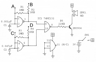
To view a more detailed version of this circuit schematic, please download the PDF at the top of this page!
The circuit consists of a pair of square-wave oscillators using two of the NAND gates of the 74HC132 chip. These oscillators consist of capacitors (C1 and C2) which charge and discharge from the outputs of the chip (pins 3 and 6) via resistors R1 and R3. Looking at the first oscillator when power is first turned on, pin 3 is high. Capacitor C1 charges from the 3v on this pin, until the voltage on it reaches the high threshold of the chip’s inputs, at which point pin 3 switches to a low level, and capacitor C1 begins to discharge, again through R1, until the voltage across it reaches the chip’s low threshold, and pin 3 goes high again. This process repeats continuously. When you touch the embroidered contacts, your body becomes part of the circuit, via R1. The resistance of your body affects the charge and discharge times, and thus the frequency of the circuit. The outputs of the two oscillators feed into a third gate of the chip, which combines the signals. R5 and the transistor form a very simple amplifier, so you can hear the output in the speaker.
Help! troubleshooting
1. If there is any problem at all, first check if the chip is hot. Be careful. Touch it quickly, as if you were testing a hot iron. If the chip is hot, immediately disconnect the battery!
a. Check that both batteries are installed correctly.
b. Check that the power to the chip isn’t wired backwards.
c. Check that you have read the colour codes properly on the resistors, and have not mixed them up.
2. If there is no sound, immediately disconnect the battery! Make sure you are using a fresh battery.
3. If there is no sound and the chip is hot. Check that there are no accidental solder-bridge connections between adjacent pins of the chip, or between other parts that shouldn’t be connected.
Reference where to get materials
electronics retailers
· Active Tech, in major cities across Canada
· Sayal Electronics, with retails stores in several cities in Ontario
· Creatron in Toronto, (They are a Canadian dealer for Sparkfun and Adafruit—see below—and stock many wearables components.)
· Addison in Montreal
Two excellent online sources:
· Digi-Key
wearable electronics retailers
· Adafruit
Reference glossary
Capacitor. A device that can store an electrical charge.
Chip. Informal name for an integrated circuit.
Circuit Board. A board, usually fiberglass, perforated with holes to mount components in.
Conductive Thread. A cotton or polyester thread that is uninsulated and incorporates metal strands.
Digital. A circuit that only has two voltage levels, high and low, represented by the binary digits 0 and 1.
Farad. A measure of capacitance, named after Michael Faraday.
Ground. The common point in a circuit, where all signals return.
Hookup Wire. Wire that’s already out the door when you wake up. It’ll maybe send you a text sometime.
Integrated Circuit (IC or chip). A component containing an entire electronic circuit fabricated on a tiny piece of silicon.
Kilo. A prefix meaning 1000. One-kilo ohm, usually written 1k-ohm, or 1 kΩ, is 1000 ohms.
Leads. (Pronounced leeds). The wires protruding from an electronic component such as a resistor.
Logic Circuit. A digital circuit.
Logic Probe. A device that can show levels in a digital circuit.
µ. The Greek letter mu, used to denote micro, i.e., 1/10000000. 1µF is read as “one microfarad” and is equal to one millionth of a farad.
µF. Microfarad. See above.
Ohm. A unit of electrical resistance, named after Georg Ohm and designated by the Greek letter omega (Ω).
Oscilloscope. A device that can show a real-time graph of voltage over time.
Ω. The Greek letter omega, used as a symbol for ohm.
Pins. The connection points of a chip, also known as legs.
Resistor. A device that limits electrical current.
Soft Circuits. Circuits made with conductive fabric components.
Transistor. A device that controls the flow of electricity.
Wearables. Short for wearable technology, a broad category that includes textile electronics such as this project.
Reference online tutorials and resources
how to solder
There is a good collection of soldering resources on the Web site of Limor Fried, an engineer and artist who makes and sells electronic kits. Also see youtube video here.
how to work with a circuit board
A page specifically about circuit-board techniques, as used in this project, can be found here. An excellent book for electronics beginners is Make: Electronics from O’Reilly media. Another good book is Getting Started in Electronics by Forrest M. Mims.
wearable links
· Social Body Lab at OCAD University
· Fashioning Technology blog
· List of e-textile resources from Margarita Benitez
· Becky Stern’s Web site has lots of good information
· Vague Terrain’s issue on wearable technology
· Twitter: Search #WearableWednesday
embroidery tutorials
Images by: Adam Coish. Schematics and diagrams by: Rob Cruickshank.