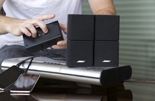
Introduction background
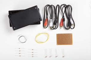
Set Up materials and tools
-
a.
1 small plastic project box (available from any electronics supplier) in which to house the mixer
-
b.
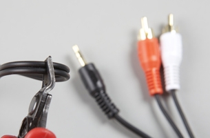
2 audio cables, each with a 3.5 mm stereo miniplug on one end, and a pair of male RCA connectors on the other end
-
c.
Rosin-core electronics solder (consider using the lead-free variety)
-
d.
Insulated hookup wire, 22 gauge, solid-core (you’ll need about a metre)
-
e.
1 piece of circuit board sized to fit the project box, [A]
-
f.
3 10k-ohm resistors coded with three bars—brown, black, and orange
-
g.
4 matching light-dependent resistors (LDRs), also known as photocells, photo resistors, or cadmium sulphide (CdS) cells
-
h.
Soldering iron with small tip, 40 watts or less
-
i.
Small wire cutters
-
j.
Wire strippers suitable for wire gauges from 26 to 20
-
k.
Needle-nose pliers
-
l.
Safety glasses or goggles
-
m.
Indelible-ink marker
-
n.
Masking tape
-
o.
Ruler marked in inches and millimetres
-
p.
Drill, with a series of drill bits 1/16 to 1/4 inch
-
q.
Glue gun with glue sticks
-
r.
Small screwdriver
Make It project specifications
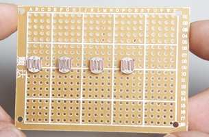
1 wire up the circuit
-
a.
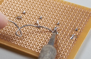
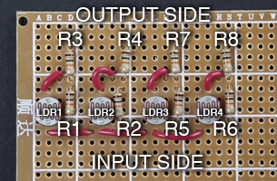
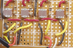
Install the LDRs on the circuit board, arranging them horizontally so that the leads are oriented vertically, and space them out so that you can control them individually.
-
b.
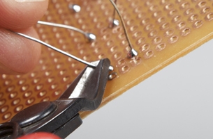
Use the wire cutters to clip the leads close to the solder.
-
c.
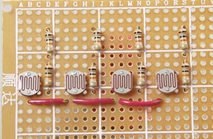
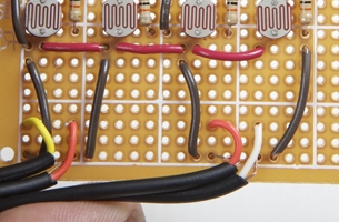
Use hookup wire to solder connections between the lower leads of all the LDRs, as shown. Note: This will become the common ground point of the circuit.
-
d.
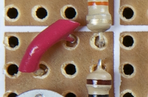
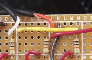
Solder a pair of 10k-ohm resistors beside each LDR, as shown.
-
e.
Solder a connection between the adjacent leads of one set of paired resistors.
-
f.
Use the free end of the hookup wire to solder the connection made in 1e to the free lead of its adjacent LDR.
-
g.
Repeat steps 1e and 1f with each set of paired resistors and each LDR.
2 prepare the mixer box
-
a.
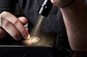
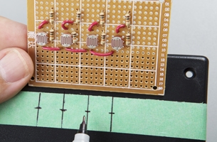
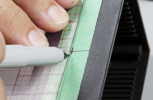
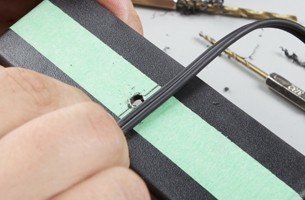
Mark on the project box the placement of the holes for the light sensors.
-
b.
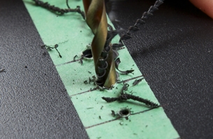
Make the holes in the project box at the point where the light sensors will go.
-
c.
Mark on the project box the placement of the hole for the audio output.
-
d.
Make the hole in the project box for the audio output.

-
e.
Follow the drilling procedure in 2d to make two holes on the opposite side of the project box, each hole to be one half inch on either side of the centre.
3 connect the audio inputs and output to the circuit
-
a.
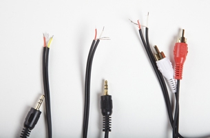
Use the wire cutters to cut the two audio cables in half.
-
b.
Strip and tin the wire ends of the audio cables.
-
c.
Feed the cut ends of the input cables and output cables through the holes made for them.
-
d.
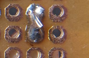
Solder each of the audio cables to the circuit board—audio inputs on one side of the circuit and the audio output on the other side of the circuit. Note: The centre conductor and the shield should be soldered into holes in the board with one or two holes between them, taking care that they cannot short together if the cable is flexed.
-
e.
Use hookup wire to connect each of the audio cables’ shield wires to the common ground point created in step 1c.
-
f.
Wire up the input side of the circuit.
-
g.
Wire up the output side of the circuit.
4 mount the circuit in the project box
-
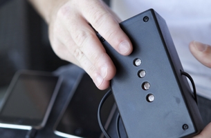
a.
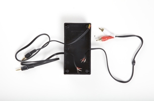
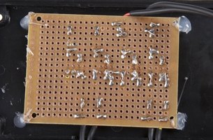
Use hot glue to secure the circuit board to the top side of the enclosure in such a way that the LDRs line up with the appropriate holes.

-
b.
Use hot glue to secure the cables in place, so that they don’t get yanked out of the board.
5 test your circuit
-
a.
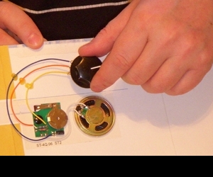
Connect the 3.5 mm stereo plugs to two audio sources, such as MP3 players or laptop computers.
-
b.
Connect the RCA plugs to the left and right inputs of an amplifier.
-
c.
Cover each LDR with a small opaque piece of cardboard. You should hear the audio from both sources, mixed together.
-
d.
Remove the piece of cardboard from one of the LDRs. Expose that LDR to a bright light, such as an LED flashlight. You should hear the corresponding audio channel drop out of the audio mix. Repeat with the other LDRs, listening for the other corresponding channels to drop out of the audio mix.
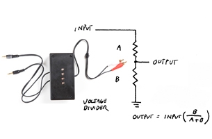
How It Works basic circuit called a voltage divider
Help! troubleshooting
Use It there are many ways to use the mixer.

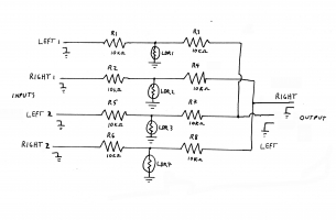
Reference light-controlled mixer circuit schematic
Reference glossary
Images by: Adam Coish. Schematics and diagrams by: Rob Cruickshank.