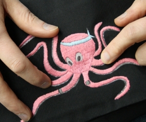
Introduction background

Circuit bending is the art of modifying existing electronics, such as children’s toys, guitar effects-units, or inexpensive battery-powered musical instruments, to create unique musical or video instruments through adding wires, knobs, and switches to control new connections within the device’s pre-existing circuit. Anyone can enjoy this inexpensive, intuitive approach to electronic exploration, with no need for prior knowledge of electronics.
 

The term circuit bending was coined by Reed Ghazala in the 1960s. The craft first emerged in the ’50s, when Serge Tcherepnin, designer of the famous ’70s Serge Modular synthesizers, conducted experiments with transistor radios, wiring various circuit points to external electrodes on the surface of the radios, which could then be “played” by touching one or more of the new electrodes, thereby using one’s skin as a variable resistor to alter the sounds created by exploiting these new connections. Ghazala rediscovered the phenomenon when a small electronic device, which he had taken out of its packaging and left in a closed drawer, accidentally and randomly short-circuited against some conductive item also in the drawer.
 

There is a growing number of circuit-bent music channels and groups on the Internet. A search within SoundCloud and Grooveshark will yield many pieces by musicians from around the world. Bent devices’ unique and unpredictable sounds make them excellent candidates for digital sampling. These samples often get orchestrated and sequenced on computers, resulting in glitchy accents in pop and rock music, which has led to an entire genre called glitch hop.  

Circuit-bent devices are used by many recording artists, including Tom Waits, Chris Cutler, Aphex Twin, Throbbing Gristle, and numerous experimental, industrial, techno, and ambient artists. There is also a plethora of purely circuit-bent performance artists and musicians out there, such as Tim Kaiser, the Ring Toss Twins, Talking Computron, Mother Daughter Crime Team, and, of course, Roth Mobot.
 

The movement isn’t limited to music. There is an entire genre of video art, called glitch, dedicated to hacking the hardware of battery-powered video devices to realize the chaotic, and often poignantly beautiful, visual results. There are groups of artists dedicated to documenting glitches in the wild by recording video glitches that take place in public displays and uploading them to various glitch groups on the Internet. 

Our type of circuit bend is called a clock bend. All digital devices have a clock, but not the type that tells the time of day; rather, it’s more like a metronome that sends start and stop signals to the circuit. On simple digital devices, like common audio greeting cards, the clock is a resistor–capacitor subcircuit. We are going to identify where the clock subcircuit is within the circuit, and hijack it with a potentiometer. Once we have control of the device’s clock, we will be able to speed it up—resulting in faster audio playback, chipmunk style; or slow it down—resulting in slower audio playback, demon-voice style. 

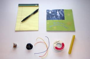
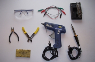
Set Up materials and tools

  • a.

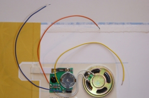
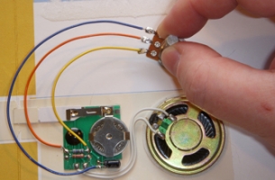
    1 digital audio greeting card.

  • b.

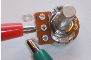
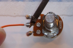
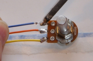
    1 500k-ohm logarithmic or linear taper potentiometer.

  • c.

    1 knob for the potentiometer (optional).

  • d.

    3 4-inch pieces of insulated solid-core hookup wire (used, of course).

  • e.

    Rosin-core electronics solder (consider using the lead-free variety).

  • f.

    1 stick of glue for use in a glue gun.

Note: Don’t, as many websites suggest, keep notes inside the device you’re bending. If you sell or give away your device, there go your notes! Remember to take notes as you bend your device.
 

  • g.

    Safety glasses or goggles.

  • h.

    3 alligator-clip leads.

  • i.

    Soldering iron stand.

  • j.

    Small wire cutters.

  • k.

    Wire strippers.

  • l.

    Hot-glue gun.

  • m.

    Soldering iron with small tip.

  • n.

    Moist sponge.


Make It project specifications

Time Required: One hour. 
Complexity: Easy. 
Cost: Less than 10 dollars.
 
Note: Only circuit bend battery-powered devices that use 9 volts or less.


What you need to know before beginning:
 
1. How to solder
a. There is a good collection of soldering resources on the website of Limor Fried, an engineer and artist.
b. You may also watch this video tutorial.
 

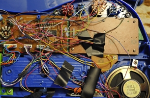
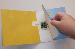
1 identify the circuit components

  • a.

    Remove the card stock surrounding the circuit within the greeting card.

  • b.

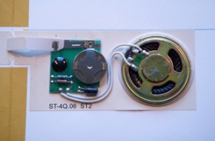
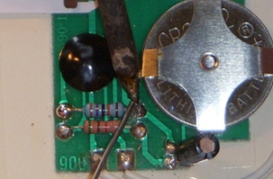
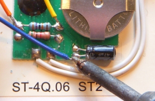
    Examine the card's circuit. Identify the basic components:


  • c.

    Start the circuit playing its audio file by gently lifting and dropping the metal wand

  • d.

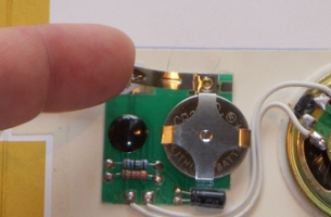
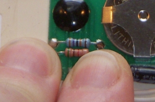
    While the circuit is playing its audio file, slightly moisten two of your fingers on the sponge and gently touch the leads on each end of one resistor. If nothing happens, repeat steps 1c and 1d on the second resistor. If you hear the card’s audio file speed up, congratulations! You have found the clock’s resistor.


2 hack the circuit to speed up the audio

  • a.

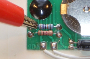
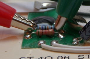
    Attach one end of the first clip lead to the clock’s resistor lead that is closest to the black blob.


  • b.

    Attach one end of the second clip lead to the clock’s resistor lead that is farthest from the black blob.


  • c.

    Test to make sure the clip leads are correctly positioned. Restart the card’s audio file by gently lifting and dropping the metal wand, moisten two of your fingers, and gently touch the two free ends of the attached clip leads. The card’s audio should speed up (touching these two clip-lead ends is the same as touching the two leads of the clock resistor).
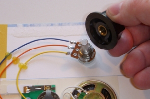
 

  • d.

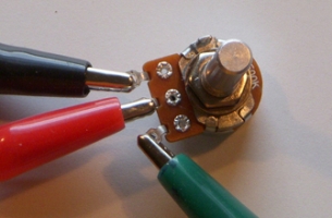
    Position the potentiometer (pot) in halfway position. Place the pot on a flat surface and position it with the shaft pointing up and the pot’s terminals positioned closest to you. Determine the pot’s halfway position by twisting the shaft clockwise until it stops and then counterclockwise until it stops. Halfway in between both stop positions is the pot’s halfway position. NB: It is important to always start with your pot in the halfway position, because turning the pot too far up or down can cause the card to crash. 


  • e.

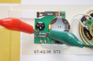
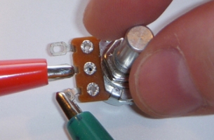
    To the centre terminal of your potentiometer attach the free end of the clip lead that is attached to the black blob-side of the clock resistor.


  • f.

    To the outer right terminal on your pot attach the free end of the clip lead that is attached to the other side of the resistor. 


  • g.

    Twist the shaft of the pot clockwise. You should hear the sound on the audio card speed up.

Note: In true hacker style, you can wire this circuit in the opposite direction. In step 2f, attach the free end of the clip lead to the pot’s outer left terminal; and in step 2g, twist the pot’s shaft counterclockwise to hear the sound on the audio card speed up. Discovering how a circuit can be hacked is the fun of circuit bending.
 

3 hack the circuit to slow down the audio

Sure, we can speed up the audio file; but how do we slow it down? There are two ways: we could completely remove the clock resistor and replace it with our potentiometer; or, a more simple method is to float the voltage. What? Don’t worry: we’ll walk you through it. And though it has a fancy name, it’s the easier of the two methods!
 
  • a.

    Identify the ground of the circuit’s capacitor. 

Note: Most audio greeting cards use electrolytic capacitors—the kind shaped like a cylinder—and they have polarity. Find the ground of the capacitor by looking for a stripe along the side of the capacitor. The capacitor leg on the striped side is attached to the ground.
 

  • b.

    Attach one end of the third clip lead to the leg on the ground side of the capacitor.

  • c.

    Attach the free end of this clip lead to the pot’s left terminal.


  • d.

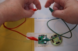
    Set the potentiometer to halfway and start the card’s audio file.

  • e.

    You should now have complete speed control of the card’s audio. If it isn’t working smoothly, try swapping the positions of the two clip leads, attaching them to opposite sides on the clock resistor’s leads.


  • f.

    After noting in your notebook, or on a piece of paper, what clip leads connect to which points on the circuit board, remove the clip leads. We are going to replace them by soldering in more permanent wiring.


4 wire up the circuit

  • a.

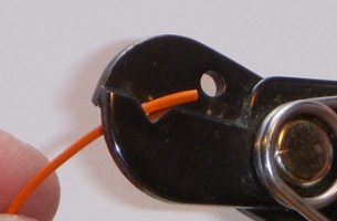
    Strip both ends of each piece of hookup wire (three pieces of wire).


  • b.

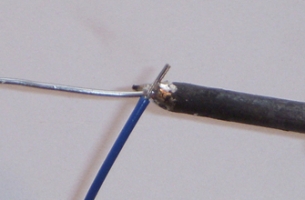
    Tin both stripped ends of each piece of hookup wire (six ends). 

Note: Tinning is explained in the glossary for this article.
 

  • c.

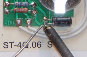
    Tin the two exposed leads of the clock resistor.

  • d.

    Tin the ground lead of the capacitor.


  • e.

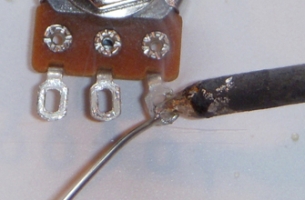
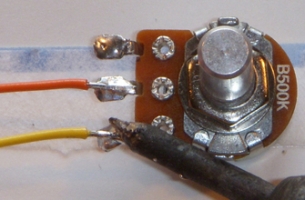
    Tin all three terminals of the potentiometer.


  • f.

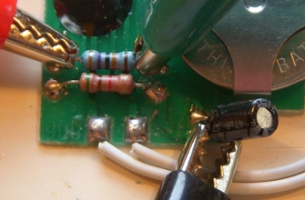
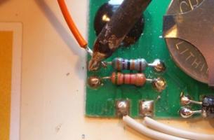
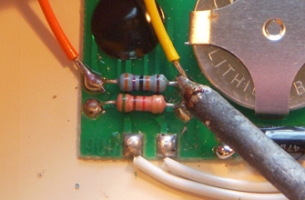
    Solder one end of the first piece of hookup wire to the clock’s resistor lead that is closest to the black blob.


  • g.

    Solder one end of the second piece of hookup wire to the clock’s resistor lead that is farthest from the black blob.


  • h.

    Solder one end of the third piece of hookup wire to the ground lead of the capacitor.


  • i.

    You should now have all three pieces of hookup wire attached to the card’s circuit.

  • j.

    Solder the free end of the first piece of hookup wire (attached to the clock’s resistor lead that is closest to the black blob) to the centre terminal of the potentiometer.


  • k.

    Solder the free end of the second piece of hookup wire (attached to the clock’s resistor lead that is farthest from the black blob) to the right terminal of the potentiometer.


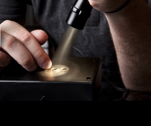
5 test and complete the circuit

  • a.

    Now for the moment of truth. Turn the shaft of the potentiometer to its halfway position, start the card’s audio, and listen to the audio playback. After turning the shaft of the potentiometer slightly clockwise, the audio should speed up. 


  • b.

    If the audio plays at its normal speed, check your connections and start the card again. If there is smoke—if the battery, your potentiometer, or the card’s circuit gets hot—stop playing the card, and proceed to the troubleshooting section of this article. 


  • c.

    Once you’re sure the speed-up function is working, solder the free end of the third piece of hookup wire (connected to the ground lead of the capacitor) to the left terminal of your potentiometer.


  • d.

    Turn the shaft of the potentiometer to its halfway position, start the card’s audio, and give the shaft a twist. You should get crazy sounds—from chipmunks to gut-wrenching demonic digital grit.


6 finish your project

  • a.

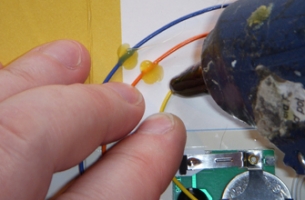
    Arrange the attached hookup wires neatly on the card, and attach each wire to the card with a dab of hot glue.


  • b.

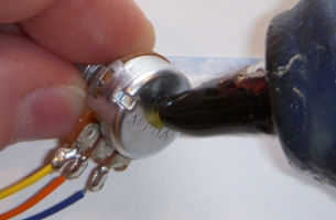
    Attach the potentiometer to the card with a small dab of hot glue.


  • c.

    If you opted for a knob to mount on the potentiometer’s shaft, now would be a good time to do that.

Note: You could remove the entire circuit from the card and mount it in a project box, like a cigar box, a plastic food container, or anything you want.
 

Important: Be sure to store your device in the clocked-up position, i.e., sped up. If you turn the potentiometer all the way to the slowed-down position and leave the device for a few hours, you will drain the battery.
 

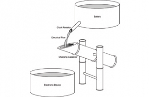
How It Works when the clock’s speed quickens the audio playback speeds up, and vice versa

In most audio-greeting-card circuits the clock’s speed determines the pitch at which the audio plays. In this circuit bend, we have replaced the circuit’s fixed clock-speed resistor with a variable resistor or potentiometer. When the clock’s speed quickens the audio playback speeds up, and vice versa.
 
The clock for the audio-greeting-card’s circuit is a classic resistor–capacitor pair. Think of the pair working like a bamboo fountain in a Zen garden: a small pipe (the resistor) governs the amount of water (electrons) that trickles into the fountain’s bamboo mechanism (the capacitor). When the bamboo mechanism is full (i.e., when it has reached its capacitance) it tips over and dumps out the water it has collected. Then the process begins again.
 
When we add a potentiometer to the circuit’s clock, it’s like adding a choke valve to the bamboo fountain. When we slow down the clock’s speed, it’s like slowing down the rate at which the small pipe fills the bamboo mechanism. When we increase the clock’s speed, it’s as if the small pipe is turned on full, filling the bamboo mechanism quickly.
 

Help! troubleshooting

If there is smoke—if the battery, your potentiometer, or the card’s circuit gets hot—stop playing the card!
 
1. The most common mistake made with clock-bent devices is trying to start the device while the new clock pot is turned too far in one direction or the other. Just return the potentiometer to its halfway position and restart the card.
 
2. Even after you’ve started the device, turning the clock too far up or down can cause it to crash. Just return the potentiometer to its halfway position and restart the card.
 
3. It’s possible that your card will start to glitch when you carefully turn the clock pot to one threshold or another. Congratulations! Glitches are one of the most sought-after kinds of bends.
 

Use It how to pick other items to hack

Many devices, like audio greeting cards and children’s toys, use a simple resistor–capacitor clock to govern their speed. Any of these devices would respond to this bending technique. The single question most often asked is: What’s a good toy to bend? When starting out in bending or hacking, a lot of people get hung up on the idea of a toy—or worse, they get hung up on the idea of a particular type of toy. There is definitely a class of holy-grail toys that historically have been used in bends, such as Speak & Spells, Speak & Reads, Speak & Learns, Speak & Maths, and Casio sk-1, sk-5, and sk-8; but these are often poor candidates for cutting one’s teeth on in electronics. By all means, if you come across any of these types of devices, squirrel them away, and when you have more experience in exploring, bending, hacking, reverse engineering, soldering, and finishing, give them a try.
 
When searching for toys to bend, you want to look for toys that play digital samples of music, sounds, or sound effects. Choose something that barks, quacks, meows, talks, or makes any interesting abstract noise. You can find these sorts of devices in thrift stores, toy stores, drug stores, department stores, and at garage sales. We prefer to get as much of our materials as possible out of the garbage. All these devices are environmentally toxic, and usually end up in a landfill somewhere, unless we pull them out and recycle or re-purpose them. We should all try to keep as much of these hazardous materials from getting too far along in the garbage system, even if it’s just a cool-looking knob off an old television set, the keys, guts, or pedals from some old organ, batteries (charged or not!), or just piles of wire lying around on the ground in alleys (usually under telephone poles).
 
Another class of device that we call “the commoner” is easily sourced and bent. This includes battery-powered radios, obscenity-shouting key chains, children’s walkie-talkies, holiday decorations, handheld digital recorders, battery-powered single-unit video games like Pac-man, and effects pedals for musical instruments—especially little delay or reverb units.
 
Another good quality to look for in a toy is sound(s) that can be interrupted or looped. This means toys that have a button you can repeatedly push to make the toy’s sound start over, or a second button you can push to immediately start another sound. Some toys have finished their assigned sample before another sample can be launched—although these devices are indeed often indeed bendable and are still plenty of fun.
 
There’s a trend in electronics towards miniaturization and cost-efficiency that manifests itself in things known as surface-mounted devices (SMDs). They are tiny versions of basic electronic components that make these devices almost impossible to bend. It’s one thing to work with a visible resistor or capacitor in a device, but it is quite a different thing to work with a little square of metal smaller than half a match head. It can be done, but requires excellent eyesight. We use a big magnifying lamp when working with these sorts of components.
 
The list of suggested items not to bend or hack is shorter: beepers (i.e., simple beeping devices), electronic games, and toxic devices.
 
By beepers we mean devices that emit a simple tone, beep, or buzz that is going to be a little boring to use—like some Disney keyboards that only have four or so big buttons and either just go beeb, boop, bup or play simple beeping or chiming melodies. They are far from ideal, but they are bendable, and can be useful for learning the basics. They can also have their boring guts dismantled and their shells used to re-house new devices; and they can sometimes provide new, better, more aesthetically pleasing interfaces for other bent devices. They can be good for making creepy versions of children’s songs.
Electronic games are usually difficult to work with. I’m referring to devices like Simon and handheld Coleco football. You want a device that you can spark up and have it emit a tone (or cool non-LCD-based video image) while both your hands are free to explore the circuit board. Games often demand too much attention, which gets in the way.
 
Toxic devices like smoke detectors and carbon monoxide detectors, are a bad idea. They are super loud and obnoxious, emit boring tones, and often contain radioactive material.Although one can bend cell phones, you should save those in your “advanced” pile.
 

Reference typical bending techniques

When searching the Internet for circuit-bending techniques, you will find people suggesting the use of clip leads or strands of wire to explore the circuit board. These techniques do work, but they are often too hot—they make too direct a connection and can cause the device to crash, or worse, fry. We prefer moistening our fingers and gently exploring the circuit board. This is also known as the lick-’n’-stick method. (Remember: only circuit bend battery-powered devices that use 9 volts or less!) Not only is the added resistance of human flesh a safety net that can prevent the device from crashing or frying, it’s a quick way to see if your newfound bend will react will with a potentiometer. It also puts you in direct contact with the circuit, making you part of the circuit for a moment—which we think is pretty neat. It’s also fast! Using this technique, we have seen circuit benders find a bend in a matter of seconds.
 

Reference types of bends

Clock. This bend changes the speed and pitch of the device’s sound.
Loop. This bend takes a sample of sound and repeats it endlessly.
Glitch. This bend scrambles the integrated circuit, resulting in random garbled noises.
Aleatoric. This bend is a type of glitch, and it generates random, yet musical, sound.
Distortion. This bend results in noisy sound.
Body Contacts. This type of bend uses the human body as a variable resistor in a circuit.
 

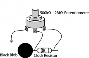
Reference circuit bend audio-greeting-card circuit diagram

To view a detailed version of this circuit diagram, please download the pdf above.

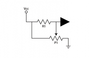
Reference circuit bend audio-greeting-card circuit schematic

To view a detailed version of this circuit diagram, please download the pdf above.
 

Reference glossary

Bend. An unplanned connection between two or more points on an existing circuit that results in unpredictable behaviour.
Capacitor. A device that stores electrical charge.
Clip lead. A pliable length of insulated wire with an alligator clip attached to each end.
Clock. A device that controls the speed of a circuit’s electrical operation.
Hack. A planned connection between two or more points on an existing circuit that results in a pre-known, predictable result.
Tinning. A soldering method that prepares all parts that are to be joined by covering each part with a small amount of solder.
Resistor. A device that limits electrical current.


Photos by: Roth Mobot. Schematics and diagrams by: Roth Mobot.