Introduction background


Set Up materials and tools

-
a.
1 small piece of circuit board.
-
b.
1 battery clip for a 9-volt battery, plus the battery.
-
c.
2 1/4” mono audio jacks.
-
d.
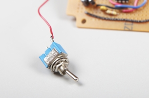
1 SPST switch for power.
-
e.
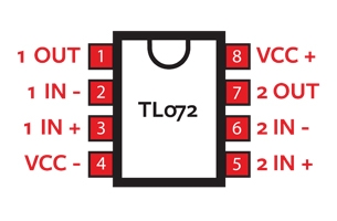
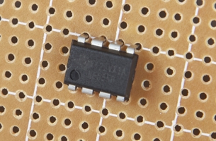
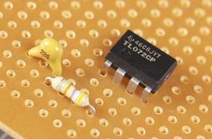
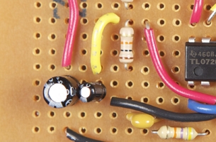
IC1 TL072 op-amp. Be sure to get the 8-pin DIP version.
-
f.
C1 and C3, 0.22µF capacitors.
-
g.
C2, 22pF capacitor. NB: Note the difference between microfarads (µF) and picofarads (pF).
-
h.
C4, 100µF electrolytic capacitor.
-
i.
C5, 10µF electrolytic capacitor.
-
j.
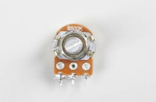
VR1, 500k-ohm logarithmic taper potentiometer (pot for short), with matching knob.
-
k.
1 each of R1, 47k-ohm 1/4-watt resistor (coded with three bars: yellow, violet, orange), R2, R3, and R6, 10k-ohm 1/4-watt resistors (coded with three bars: brown, black, orange), R4, 4.7k-ohm 1/4-watt resistor (coded with three bars: yellow, violet, red), and R5, 33k-ohm 1/4-watt resistor (coded with three bars: orange, orange, orange).
-
l.
D1, D2, 1N914 general purpose diodes.
-
m.
1 tea-tin or similar tin box large enough to fit the circuit and wide enough to provide clearance for 1/4” jacks.
-
n.
Double-sided foam tape, duct tape, and some soft sponge foam for mounting the circuit and batter
-
o.
Insulated solid-core 24-gauge hookup wire.
-
p.
Insulated stranded-core 24-gauge hookup wire
-
q.
Rosin-core electronics solder (consider using the lead-free variety).
-
r.
Safety glasses or goggles.
-
s.
Small wire cutters.
-
t.
Wire strippers.
-
u.
Needle-nose pliers.
-
v.
Soldering iron, with a small tip, 40 watts or less.
-
w.
1 helping hands tool.
-
x.
Scissors.
-
y.
Drill, with series of drill bits 1/16” to 3/8”. A step bit such as a Unibit is best.
-
z.
1 small metal file.
Make It project specifications
1 mount the IC1 chip to the circuit board
-
a.
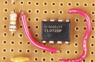
Identify pin 1 of your IC1 chip. The key to identifying the pins is finding pin 1, which is to the left of the semicircular indentation at the end of the chip. The remaining pins are numbered 2 through 8 counterclockwise around the chip.

-
b.
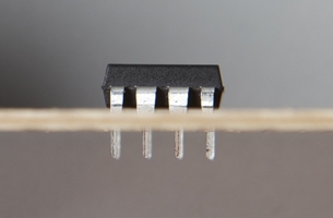
Straighten the pins of the chip if they are not at right angles to the chip. Straighten them by slightly bending them on a flat surface, as shown.
-
c.
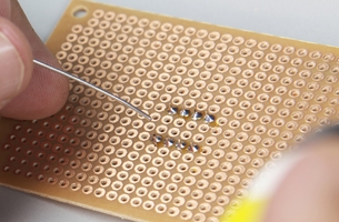
Orient the chip on the circuit board, making sure that pin 1 is positioned to the lower left, as shown.
-
d.
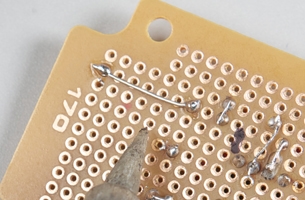
You will solder and make connections on the underside of the board, so make sure all the pins of the chip go through the board, and are not bent underneath the chip. Don’t force them.
-
e.
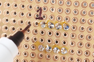
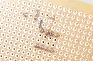
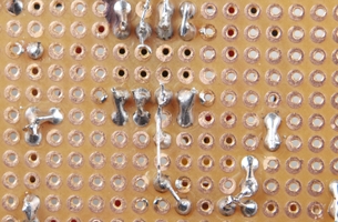
Flip the board upside down and fix the chip in place by soldering all eight pins.
-
f.
Mark pin 1. On the underside of the board, with an indelible marker write 1 to keep the correct orientation when you’re working on the circuit board.
2 Wire up the circuit
-
a.
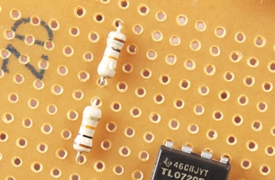
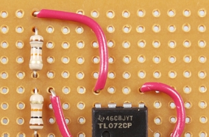
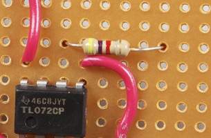
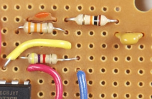
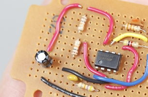
Mount the C1, 0.22µF capacitor and R1, 47k-ohm resistor as shown.
-
b.
Connect one side of C1 to R1, and the other side of R1 to pin 2 of IC1. The other side of C1 will be connected later.
-
c.
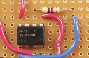
Mount R2 and R3 as shown and connect one end of R2 to one end of R3.
-
d.
Connect the junction of R2 and R3 to pin 3 of IC1.
-
e.
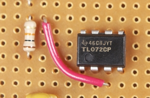
Using a short piece of wire, connect pin 3 to pin 5 of IC1.
-
f.
Connect a short piece of hookup wire on the underside of the board as shown, from the bottom point of R3. This will be the ground point of this circuit.
-
g.
Connect the free end of R2 with a short piece of wire to pin 8 of IC1.
-
h.
Using a short piece of hookup wire, connect pin 4 of IC1 to the common ground point you made previously.
-
i.
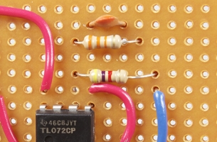
Mount R4 as shown.
-
j.
Connect one end of R4 to pin 6 of IC1. Then, with a short piece of wire, connect the other end to pin 1.
-
k.
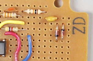
Mount C2 and R5 as shown and connect each lead of C2 to the corresponding lead of R5.
-
l.
Connect one lead of R5 to pin 6 and, using a piece of hookup wire, connect the other lead of R5 to pin 7 of IC1.
-
m.
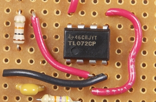
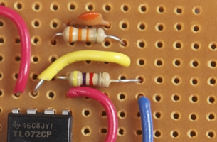
Mount R6 and C3 as shown.
-
n.
Connect one end of R6 to pin 7 of IC1, and the other end of R6 to C3.
-
o.
Mount the diodes, D1 and D2 as shown. Make sure the stripes are oriented opposite to each other. Connect D1, D2, and the free end of C3 together.
-
p.
Connect the other ends of D1 and D2 together and connect this to the circuit ground.
-
q.
Mount C4, noting the polarity of the leads. Connect the negative (-) lead to the circuit ground.Connect the positive (+) lead to the top end of R2.
-
r.
Mount C5 connecting the (-) lead to the ground and the (+) lead to the junction of R2 and R3.
3 mount jacks, switches, and pot to the circuit
-
a.
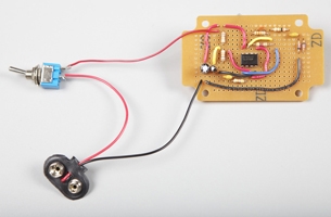
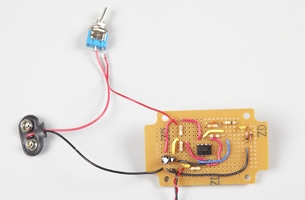
Take a piece of stranded hookup wire and connect one side of switch S1 to the junction of R2 and C4.
-
b.
Connect the black lead of the 9V battery clip to the circuit ground. Connect the red wire of the 9V battery clip to the free side of the S1 switch.
-
c.
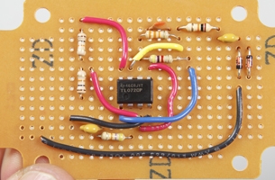
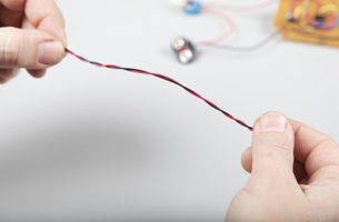
Take two different-coloured pieces of stranded hookup wire and twist them together.
-
d.
Connect one wire of this pair to the free end of C1 and the same end of the other wire to the circuit ground.
-
e.
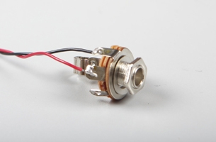
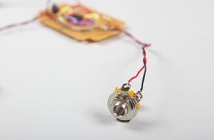
Take the free ends of the two wires and connect the one from C1 to the “tip” contact of the input jack, then connect the one from the circuit ground to the ground terminal of the input jack.
-
f.
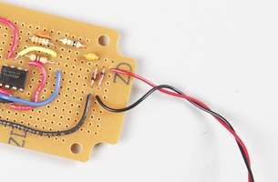
Take another pair of different-coloured pieces of stranded hookup wire and twist them together. Connect one wire of this pair to the junction of D1, D2, and C3, and connect same end of the other wire to the circuit ground.
-
g.
Take the free ends of the two wires and connect the one from the circuit junction to the “tip” contact of the output jack, then connect the one from the circuit ground to the ground terminal of the output jack.
-
h.
Place the potentiometer on a flat surface and position it with the shaft pointing up and the terminals pointing toward you then connect a short piece of hookup wire between the left-hand terminal, and the centre terminal.
-
i.
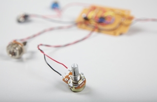
Take another pair of different-coloured pieces of stranded hookup wire and twist them together. Connect one wire of this pair to pin 2 of IC1, and connect the same end of the other wire to pin 1 of IC1. Take the free ends of the two wires and connect them to the left and right terminals of the potentiometer respectively, as shown.
4 mount the components
-
a.
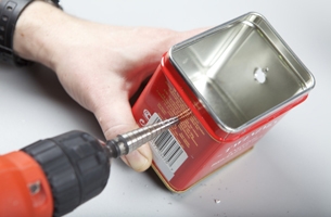
Using a power drill, and starting with the smallest bit you have, drill two 3/8” holes into each side of the tin, one for the input jack and one for the output jack. Deburr the edges of the drilled hole with a metal file. Make sure the box is big enough to allow clearance for the plugs when they are inserted.
-
b.
Using a power drill, again starting with the smallest bit you have, drill two 1/4” holes into the front of the tin, one for the potentiometer and one for the switch. Switches normally require 1/4” mounting holes, but measure your switch to check. Vacuum the metal shavings out of the tin to ensure that no short circuits occur.
-
c.
Use a couple of layers of duct tape to insulate the inside of the tin. You will later attach the board to it with double-sided tape, but only after you’ve tested the circuit.

-
d.
Mount the switches and jacks from the inside of the tin and tighten all nuts.
-
e.
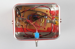
Place the circuit board at the bottom of the tin and place a piece of foam, cut to size, on top of the circuit. Connect the battery to the battery holder and place the battery on top of the foam. Cut some foam pieces to hold the battery in place, and attach them to the tin with double-sided tape.
-
f.
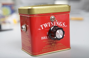
Turn the potentiometer fully counterclockwise and attach the knob so that the pointer is in the seven-o’clock position.
5 test your circuit
-
a.
Turn the fuzzbox on.
-
b.
Turn the volume on your guitar amp all the way down and plug the output of the fuzzbox into the input of your amp.
-
c.
Plug your instrument into the fuzzbox, and turn up the volume on your amp slightly.
-
d.
Turn up the potentiometer on the fuzzbox about a quarter of the way, and play your instrument.
-
e.
Adjust the potentiometer for the desired amount of distortion. You can also use the volume knob on your instrument to control the level to the fuzzbox, and therefore the amount of distortion.
-
f.
If you hear nothing, or hear only a hum or noise, disconnect the battery immediately, and proceed to the troubleshooting section of this article.
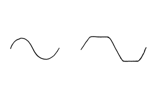
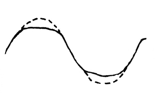
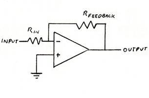
How It Works two op-amps cascaded in two stages
Help! troubleshooting
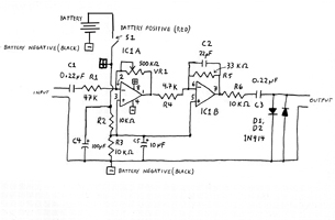
Reference fuzz-box schematic
Reference glossary