Introduction background

Binaural recording is a recording method that attempts to preserve the natural “3-D” perception of sound. Our ability to perceive the location of sounds we hear is the result of many complex factors, including the spacing of our ears and the acoustic properties of our heads. Binaural recording differs from mere stereophonic recording in that it takes these factors into account, as well as targeting the ears separately in the playback system, so the left ear hears only the signal intended for it, with none of the signal intended for the right ear, and vice versa. For this reason, you must wear headphones to listen to a binaural recording, just as you must wear special glasses to watch a 3-D movie. The results can be startling; listeners often pull off the headphones to establish whether the sounds are recorded or not. 
 

Over the years a number of artists and musicians have worked with the technique, among them Lou Reed on Street Hassle [1978] and Pearl Jam on Binaural [2000]. The Canadian artist Janet Cardiff has used binaural recording extensively, most notably in her Walks series.
Binaural recording is still a fringe activity, and while the popularity of low-cost portable digital recorders have made field recording accessible to many sound enthusiasts, binaural mikes still remain prohibitively expensive. In this DIY we provide instructions for making a set of high-quality binaural microphones for under twenty-five dollars.
 

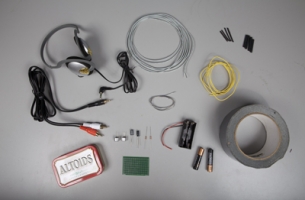
Set Up materials and tools

  • a.

    1 small piece of circuit board.

  • b.

    2 2200-ohm resistors, coded with three red bars.

  • c.

    2 1 µF electrolytic capacitors.

  • d.

    1 battery holder for 2 AAAs, and the two batteries.

  • e.

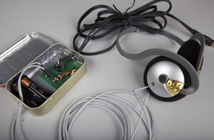
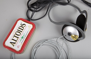
    1 Altoids or similar tin.

  • f.

    2 electret microphone capsules.

  • g.

    1 set of headphones to dismantle.

  • h.

    1 audio cable, 3.5 mm plug to 2 RCA plugs.

  • i.

    Insulated hookup wire, 22 gauge or smaller.

  • j.

    Rosin-core electronics solder (consider using lead-free variety).

  • k.

    Heat-shrink tubing, sized to fit your mike cable (6 inches).

  • l.

    Heat-shrink tubing, sized smaller than 6 inches, for insulating microphone capsule connections.

  • m.

    Lightweight card stock, such as for a file folder, cut to the size of the tin (not pictured).

  • n.

    Duct tape and masking tape (not pictured).

  • o.

    Small-diameter mike cable(6 feet or more), one conductor with shield.

  • p.

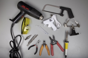
    Safety glasses or goggles. Please wear them!

  • q.

    Small wire cutters.

  • r.

    Wire strippers.

  • s.

    Needle-nose pliers.

  • t.

    Soldering iron, with a small tip, 40 watts or less.

  • u.

    1 helping hands tool.

  • v.

    Scissors.

  • w.

    Hacksaw, to trim circuit board, if necessary.

  • x.

    Heat gun or cigarette lighter for shrinking heat-shrink. A hair drier won’t work!

  • y.

    Drill, with series of drill bits 1/16 to 1/4 inch. A step bit such as a Unibit is best, although they’re expensive.

  • z.

    Glue gun with glue sticks.

Make It project specifications

Time Required: An afternoon. 
Complexity: Moderate. 
Cost: 10–25 dollars .
 

What you need to know before beginning:
 
1. How to solder
a. There is a good collection of soldering resources on the website of Limor Fried, an engineer and artist.
b. You may also watch this video tutorial.
 
2. How to work with a circuit board
a. You may refer to  this website specifically about circuit-board techniques, as used in this project.
b. An excellent book for electronics beginners is Make: Electronics, from O’Reilly media.


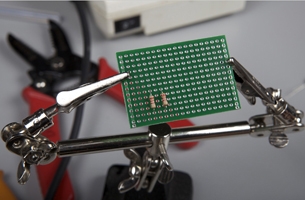
1 make the power circuit
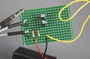
Mount the resistors and capacitors on the circuit board
 
  • a.

    Use a hacksaw to cut the circuit board to 2 in. x 1.5 in.


  • b.

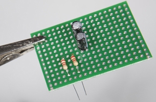
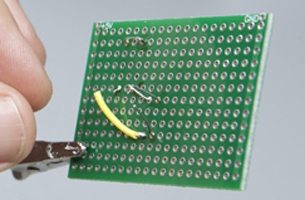
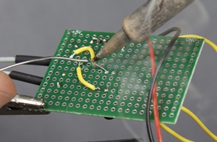
    Mount the resistors on the circuit board in approximately the locations pictured, leaving the leads closest to you untrimmed. 

  • c.

    Bend the untrimmed lead of second resistor to the soldered lead of first resistor and solder a connection between the two. 

  • d.

    Mount the capacitors on the circuit board in approximately the locations pictured.


Make connection between capacitors and resistors
 
  • e.

    Using a length of hookup wire, solder a connection between the positive side (+) of a capacitor and one of the resistors.

  • f.

    Repeat step 1e for other resistor and capacitor pair. 

 Connect the battery holder to the circuit board
 
  • g.

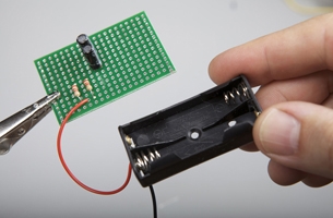
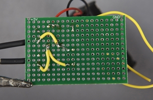
    Solder the red wire (+) of the battery holder to the junction of the two bias resistors. 

  • h.

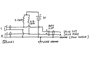
    Solder the black wire (-) of the battery holder to the circuit board in approximately the location pictured. See figure 1, point E. 

Note: Don’t connect the battery until the circuit is finished and you are ready to test it. 
 

  • i.

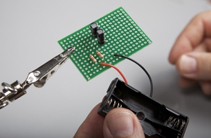
    Solder a length of hookup wire to the circuit board in approximately the location pictured. 

  • j.

    Solder a connection between the black wire of the battery holder and the hookup wire referred to in the previous step. 

Note: This will become the common ground for the circuit.
 

2 attach the microphone cables to circuit

  • a.

    Cut the six-foot section of mike cable into two equal pieces.


  • b.

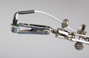
    Cut a length of the larger-diameter heat-shrink tubing and slip it over one end of one of the mike cables.
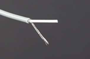
Note: Do not shrink the heat-shrink just yet. Move it out along the length of the cable and out of the way. 
 

  • c.

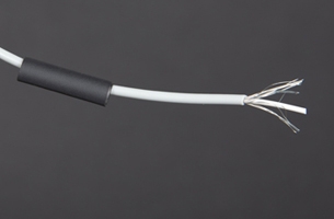
    Remove approximately 1inch of cable jacket with wire strippers 

Note: Take care not to damage the shield. 
 

  • d.

    Twist the shield strands together. 


  • e.

    Strip a small piece of insulation off of the centre conductor. 
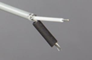
 

  • f.

    Cut a small piece of heat-shrink tubing to cover all but 1/4 inch of the shield, and shrink in place with the heat gun.
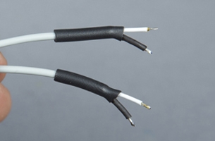
 

  • g.

    Slide larger heat-shrink tubing down over the edge of the cable jacket. It should cover the cut edge, but leave the shield and centre conductor long enough to connect to the circuit board. 


  • h.

    Shrink in place.


  • i.

    Repeat these steps for the second piece of mike cable.


Solder mike cables to circuit
 
  • j.

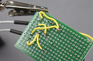
    Solder one of the mike cables (both twisted shield and the centre conductor) to the circuit board, taking care not to short the shield to the centre conductor. 

Note: Applying too much heat to the shield will melt the cable jacket and cause a short in the circuit. 
 

  • k.

    Repeat with second mike cable.


  • l.

    Using a length of hookup wire, solder a connection between the centre conductor of one mike cable to the junction of one bias resistor and its paired capacitor. 

  • m.

    Solder a connection between the centre conductor of the second mike cable to the junction of   the other bias resistor and its paired capacitor. 

  • n.

    Using hookup wire, connect the shields of both mike cables to the common ground point made in step 1c.


3 attach the audio output cables to circuit

  • a.

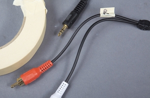
    With a piece of masking tape, label the audio cable attached to the red plug. 
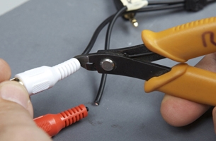
Note: The red plug indicates that this is the right output. 
 

  • b.

    Using wire cutters, remove the RCA plugs. 
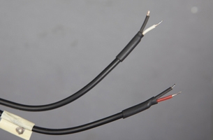
 

  • c.

    Strip and prepare the ends of the audio cables as in 2b through 2i.
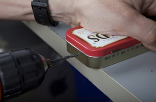
 

  • d.

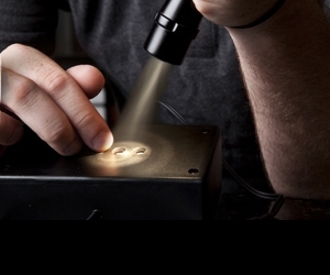
    Using a power drill, carefully drill a hole into each end of the tin. Start with the smallest bit you have, and gradually work the hole up to the proper size, using progressively larger bits. Make it only as big as it needs to be for the cables. The larger it is, the more ragged it will get. If you have a step bit such as a Unibit, use it here. 
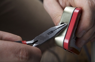
 

  • e.

    Deburr the edges of the drilled hole with needle-nose pliers. Or, if you have a small round file, use it to smooth the edges of the hole. 


  • f.

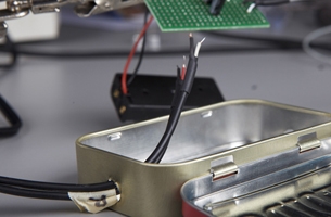
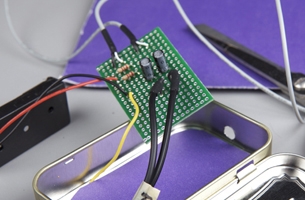
    Route the free ends of the audio cables through one hole in the tin. 


  • g.

    Solder the centre conductor of the red-labelled cable and its twisted shield to the circuit board, taking care not to short the shield to the centre conductor.

Note: Applying too much heat to the shield will melt the cable jacket and cause a short in the circuit. 
 

  • h.

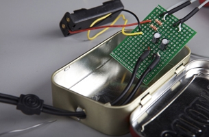
    Repeat with second audio cable.


  • i.

    Using a piece of hookup wire, solder a connection between the centre conductor of the red‑labelled audio cable to the negative side (-) of one of the capacitors.

  • j.

    Using a piece of hookup wire, solder a connection between the centre conductor of the second audio cable to the to the negative side (-) of the other capacitor.

4 fit circuit into tin

  • a.

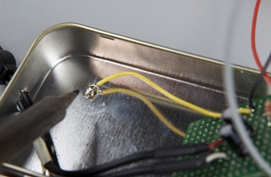
    Solder the free end of the ground lead to the bottom of the tin. 


  • b.

    Cut a piece of cardboard to fit the bottom of the tin and place it into the tin, making sure the ground lead comes out and over the cardboard.


  • c.

    Cover the cardboard and all inside surfaces of the tin with duct tape, taping the cardboard to the sides and bottom of the tin. 


  • d.

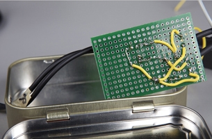
    Route the free ends of the mike cables from inside the tin through the remaining open hole in the tin.
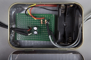
 

  • e.

    Place the circuit board into one end of the tin and the battery holder beside it.


5 connect the microphone capsules

  • a.

    Prepare the free end of one mike cable as in steps 2b through 2e.


  • b.

    Cut a small piece of heat-shrink tubing to cover all but a 1/2 inch of the shield, and shrink in place with the heat gun.


  • c.

    Slide larger heat-shrink tubing down over the edge of the cable jacket. It should cover the cut edge but leave the shield and centre conductor long enough to connect the microphone capsule terminals. 


  • d.

    Shrink in place.


  • e.

    Repeat steps 5a through 5d for the free end of the second mike cable.


  • f.

    Cut 2 small pieces of heat-shrink tubing the length of the microphone capsule terminals and slide over both the shield and conductor of the mike cable. 
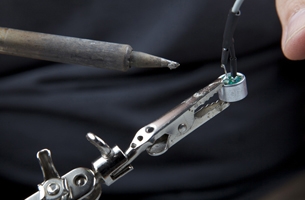
Note: Do not shrink them yet.
 

Solder mike cables to microphone capsules
 
  • g.

    Solder the centre conductor of one of the mike cables to the positive terminal (+) of the microphone capsule. 

Note: If the microphone capsule comes with leads rather than terminals, solder it to the red lead and insulate it with a small piece of heat-shrink.
 

  • h.

    Solder the mike cable shield to the negative terminal (-) of the microphone capsule. 
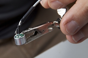
Note: If the microphone capsule comes with leads rather than terminals, solder it to the black lead and insulate it with a small piece of heat-shrink.
 

  • i.

    Slide small heat-shrink tubing down over the soldered microphone capsule terminals and shrink in place. 


  • j.

    Repeat steps 5a-i with other microphone capsule.


6 test your equipment

  • a.

    Connect the audio output to your recorder microphone input.


  • b.

    Connect the batteries.


  • c.

    Put recorder into record mode and make distinct sounds into the left and right capsules.


  • d.

    Monitor recording to ensure that you are getting signal from both capsules, that the left capsule is the left signal, and vice versa.


7 finishing the project

  • a.

    Hot glue the circuit board into the tin.


  • b.

    Hot glue the cables into the centre of the holes in the tin, ensuring that cables are centred in the hole and are not catching any rough edges.


8 fabricate the microphone head mount

  • a.

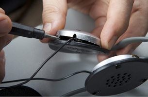
    With a small screwdriver, remove the earpieces from the headset.
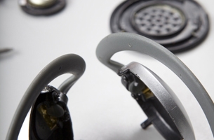
 

  • b.

    Remove the small speakers from the earpieces and discard the speakers and cable.


  • c.

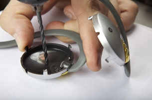
    Drill a hole that’s the diameter of the microphone capsule into the centre of the headphone earpiece. Take extra care when drilling not to crack the plastic. Use a step bit if you have one. You may want to drill a small hole and enlarge it with a small round file. 


  • d.

    Fit microphone capsule through the earpiece holes so they are facing outward. Make sure that the left microphone capsule is in the left earpiece and vice versa.


  • e.

    Secure the microphone capsule with hot glue into the earpieces, ensuring that the fronts of the capsules don’t get covered with glue.


  • f.

    Route the mike cables in the manner of the original headphone cables.


  • g.

    Secure mike cables with hot glue for strain relief.


  • h.

    Cover the microphone capsules’ wire connections with hot glue in order to secure wiring.


  • i.

    Reinstall the earpieces on the headset, making sure to route the cables in the manner of the original headphone cables.


Help! troubleshooting

After you complete the circuit and run the test you should hear distinct sounds on the left channel and the right channel.
 
1. If there is no sound at all on the recording:
a. Check that all your connections are correct by looking at the circuit figure, as well as the photographs. You may wish to enlist a friend’s help: sometimes a fresh pair of eyes can spot a mistake that you’ve been staring at for an hour!
b. Check that you are plugged into the mike input of your recorder, not the line input.
c. Check that your batteries are fresh, and installed properly.
d. Check that the black and red wires from the battery holder are connected properly.
e. Check for short circuits. Pay particular attention to the mike cables and output cables—an overheated shield can easily melt into the centre conductor.
f. Check that the microphone capsules are wired the correct way around—if you are in doubt, try reversing the connection to one of them.
 
2. If there is a loud hum on the recording:
a. Check that all the connections to the common ground are made correctly. This includes the shields of the mike cables, the shields of the output cables, the black wire of the battery holder, and the ground wire to the case.
 
3. If there is a quiet hum or buzz on the recording:
a. Check that the ground wire is securely soldered to the bottom of the tin.
b. Make sure you are using good quality cable, and that it’s no longer than six feet.
c. Ensure that your recorder is running on batteries, not the AC adaptor, and that you are a good distance from such things as fluorescent lights and computers.
d. Ensure that you are not touching the microphone capsules, or any other electrical connection. 
 

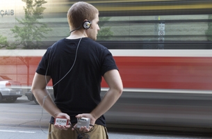
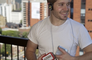
Use It binaural microphone technique

Now, take the recorder out, and use it! First, you’ll need a head on which to place the microphones. We suggest using the head you were born with. The binaural effect depends on the acoustic properties of the human head, and while commercial binaural mikes often use simulated human heads, these are prohibitively expensive.
Using your own head has disadvantages and advantages. You must remain very still, as you don’t want movement sounds to interfere with your recording. If you take a sound walk, pay particular attention to the position of your head. Turning your head will rotate the sound field for the listener, and could be disorienting. The microphone is particularly sensitive to wind noise. If you use it outdoors, be aware that any windsock material, such as extra foam-headphone pads, may affect the spatialization of sound. You may have to make a trade-off between wind noise and a good binaural effect.
You can’t monitor the recording with headphones, since, even if you managed to squeeze a pair of earbuds under the microphones, you could generate feedback or induce phase-shift errors that would spoil the spatialization. On the other hand, there is some evidence that small head-movements serve a role in localizing sounds, particularly in determining whether a sound is in front of or behind you. 
 

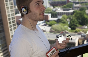
Use It record and experiment

Put the headset on, and find some interesting sounds to record. Sound sources that have intrinsic movement are the most effective to record binaurally, such as air and road traffic.   
        
Try dramatic effects, such as having someone whisper in your ear while recording. It is particularly interesting to listen to a recording in the space in which it was made. This experience is used extensively in Janet Cardiff’s works. Try, for instance, recording a noisy dinner, then listen to the recording while seated in the now-empty dining room.
 
If you have any artificial heads—such as wig heads, mannequin heads, or hairdresser’s practice heads—try the mike with them, and compare the results with a real, moving human head. Some other parameters to experiment with are skin texture, head density, hair covering, and ear shape. 
 

Use It listen

When you listen to your recordings, you must do so with headphones. Try to get the best over-the-ear style headphones you can. Listen for how sounds are positioned in space.
You may want to hear what others have done: a good place to start is the Freesound Project: <www.freesound.org/> Do a search for “binaural”on the Freesound site and you will find hundreds of binaurally recorded soundscapes.
Janet Cardiff has excerpts from her walks at <www.cardiffmiller.com/artworks/walks/index.html>.


Reference binaural microphone circuit schematic

To view the binaural microphone circuit schematic in detail, please download the PDF above.

Reference glossary

AC. Alternating Current—in this case, the signal from the microphone.
DC. Direct Current—in this case the battery voltage.
Bias Voltage. A DC voltage applied to an AC signal point in a circuit. In this case, the battery voltage is applied to the mikerophone output, to provide the proper conditions for the transistor amplifier in the microphone capsule.
Capacitor. A device that stores electrical charge. It is used in this circuit to block the DC bias voltage from reaching the audio output.
Circuit Board. A board, usually fiberglass, perforated with holes on which to mount components.
Electret. A material analogous to a magnet, which has a permanent electric charge. It is used to make inexpensive high-quality microphones.
Ground. The common point in a circuit, where all signals return.
Resistor. A device that limits electrical current.
Wire Gauge. A system for specifying wire sizes. Smaller diameter wires have larger gauge numbers.
Shield. A braided or twisted ground wire that surrounds the signal conductors in a cable. 


Images by: Adam Coish. Schematics and diagrams by: Rob Cruickshank.