Introduction background


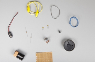
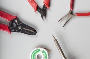
Set Up materials and tools
-
a.
1 small piece of circuit board.
-
b.
1 1k-ohm quarter-watt resistor (coded with three bars: brown, black, and red).
-
c.
1 150-ohm quarter-watt resistor (coded with three bars: brown, green, and brown).
-
d.
1 0.1 µF capacitor (usually marked 104).
-
e.
1 0.01 µF capacitor (usually marked 103).
-
f.
1 battery holder for a 9-volt battery.
-
g.
1 555 timer chip. The chip you want should be an NE555 or an LM555, or be compatible with those, and be in an 8pin DIP package.
-
h.
1 8-ohm speaker.
-
i.
1 alligator-clip test lead.
-
j.
1 100k-ohm potentiometer. Audio taper (type “a”) is best, but linear (type “b”) will work just fine.
-
k.
1 9-volt battery.
-
l.
Insulated hookup wire, 22 gauge or smaller.
-
m.
Rosin-core electronics solder (consider using lead-free variety).
-
n.
Soldering iron, with a small tip, 40 watts or less.
-
o.
Wire strippers.
-
p.
Small wire cutters.
-
q.
Needle-nose pliers.
-
r.
1 set of helping hands (not pictured).
-
s.
1 indelible-ink marker (not pictured).
-
t.
Safety glasses or goggles (not pictured). Please wear them!
Make It project specifications
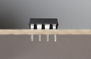
1 prepare the 555 timer chip
![]()
-
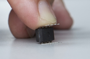
a.
Identify pin 1 of your chip. The key to identifying the pins is finding pin 1, which is to the left of the circular indentation at the uppermost corner of the chip. The remaining pins are numbered 2 through 8 in a counter-clockwise direction around the chip.
-
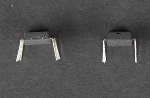
b.
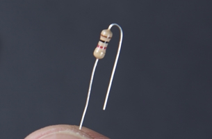
Check the pins of your chip. When the chip is manufactured, the pins are not often at right angles to the chip, which prevents the chip from fitting into the holes of the circuit board.
-
c.
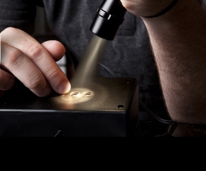
Straighten the pins of the chip if they are not at right angles to the chip, straighten the pins of the chip. Do this by slightly bending them on a flat surface, as shown.
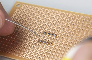
2 mount the 555 timer chip to the circuit board
-
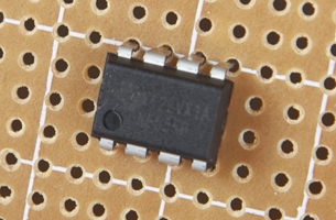
a.
Orient the chip on the circuit board, making sure that pin 1 is positioned to the lower left, as shown.
-
b.
You will solder and make connections on the underside of the board, so make sure all the pins of the chip go through the board, and are not bent underneath the chip. Don’t force them.
-
c.
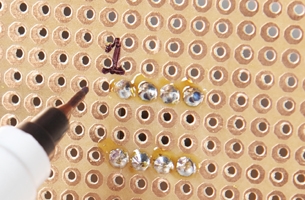
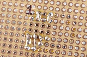
Flip the board upside down and solder the chip in place at all eight pins.
-
d.
Mark pin 1. On the underside of the board, with an indelible marker write 1 to keep the correct orientation when you’re working on the circuit board. Note: Because this is a mirror image of the board top, the remaining pins are numbered 2 through 8 in a clockwise fashion around the chip.
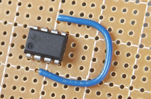
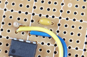
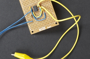
3 wire up the circuit
-
a.
Using a length of hookup wire, solder a connection between pins 6 and 2 of the chip.

-
b.
Using a length of hookup wire, solder a connection between pins 4 and 8 of the chip.
-
c.
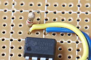
Prepare the 1k-ohm resistor, bending leads as shown.
-
d.
Mount the 1k-ohm resistor as shown.
-
e.
Solder a connection between the other lead of the resistor to pin 7 of the chip.
-
f.
Solder a connection between one lead of the resistor to pin 8 of the chip.
-
g.
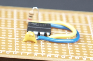
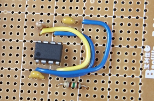
Mount the first 0.1 µF capacitor as shown.
-
h.
Solder a connection between one lead of the capacitor to pin 1 of the chip.
-
i.
Solder a connection between the other lead of the capacitor to pin 2 of the chip.
-
j.
Mount the second 0.01 µF capacitor as shown.
-
k.
Solder a connection between one lead of the second capacitor and pin 5 of the chip.
-
l.
Using a length of hookup wire, solder a connection between the other lead of the second capacitor and pin 1 of the chip.
-
m.
Mount the 150-ohm resistor as shown.
-
n.
Solder a connection between one lead of the resistor to pin 4 of the chip.
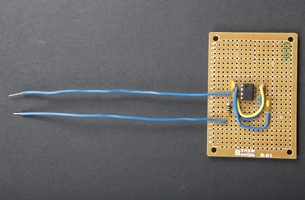
4 mount the loudspeaker to the circuit
-
a.
Cut a 3-inch piece of hookup wire and solder it to pin 3 of the chip.
-
b.
Cut a 3-inch piece of hookup wire and solder it to the free end of the 150-ohm resistor, as shown. These will be your loudspeaker leads.
-
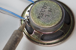
c.
Solder your speaker leads directly to your loudspeaker, as shown.
-
d.
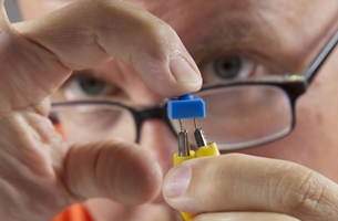
Cut the alligator-clip lead in half, and strip the cut ends as shown.
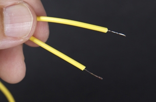
-
e.
“Tin” the leads with a small amount of solder, to keep them from fraying.
-
f.
Solder the stripped end of one alligator clip to pin 6 of the chip, and the other clip to pin 7 of the chip, as shown.
-
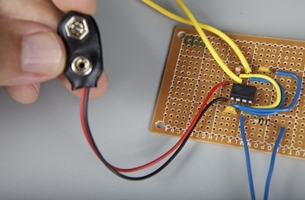
g.
Solder the red lead from the battery clip to pin 8 of the chip.
-
h.
Solder the black lead from the battery clip to pin 1 of the chip, as shown.
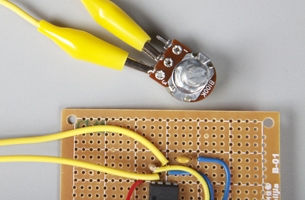
5 test your circuit
-
a.
Connect one alligator-clip lead to the middle terminal of the 100k-ohm potentiometer and another to one of the outer terminals, as shown. Leave the other terminal free. Set the potentiometer to about mid-point.
-
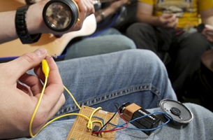
b.
Connect the 9-volt battery. You should hear a tone from the speaker.
How It Works resistor-capacitor combination
Help! troubleshooting
Use It various resistors

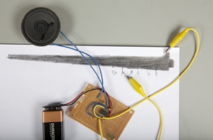
Use It pencil drawings
Use It more ideas

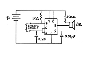
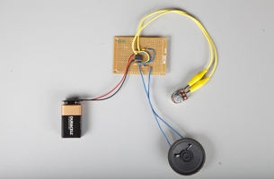
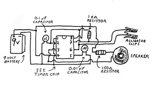
Reference tone generator circuit diagram

Reference tone generator circuit schematic